 Optical Transport Networking Solution
 FTTH Solution
 Home Networking Solution
 POL Solution
 Outdoor OLT Solution
 More
More
 Brand News
 Product News
 Tech Blogs
 CMS
CMS
 Tech Support
 Document Download
 Software Download
 FAQ
FAQ
 Training Center
 About Us
 Careers
 Partners
 Quality Assurance
 Video Center


This website uses cookies to ensure you get the best experience. Some cookies are essential, while others help
us improve your experience by analyzing data or showing personalized content.
For details, please see our
Privacy Policy.

In carrier fiber access networks, the OLT is not an isolated device. It sits between the subscriber-side PON network and the operator's core network, forwarding traffic from multiple ONUs toward aggregation switches, which in turn connect to routers, BRAS/BNG systems, and the core network.
For ISPs, telecom operators, campus networks, hotels, communities, and enterprise fiber access projects, understanding how an OLT connects to the core network is essential. It helps network planners design appropriate uplink bandwidth, VLAN structure, redundancy, traffic control, and long-term expansion.
This article explains how an OLT connects to the upstream network and integrates with switches in carrier PON deployments.
An OLT, or Optical Line Terminal, is the operator-side access device in a Passive Optical Network. It connects downward to ONUs or ONTs through passive optical splitters and connects upward to the carrier's aggregation or core network through uplink interfaces.
A typical carrier access path looks like this:
Core network → aggregation switch / router → OLT → optical splitter → ONU / ONT → end user
In this architecture, the OLT works as the access aggregation point for fiber subscribers. It aggregates PON traffic from the user-side ONUs, applies service rules, and forwards traffic to the aggregation network through its Ethernet uplink interfaces..
Broadband Forum TR-156 describes the OLT as "the first aggregation point in GPON access scenarios." This is a useful way to understand its role: the OLT collects traffic from many ONUs and sends it toward the operator network through uplink ports. Source: Broadband Forum TR-156
For example, a C-Data OLT can be used in FTTH, FTTB, campus, hotel, and ISP access networks to connect multiple subscriber-side ONUs to the carrier or enterprise backbone.
An OLT connects to the core network through its uplink ports. These uplink ports are usually connected to aggregation switches, Layer 3 switches, routers, or metro Ethernet network equipment.
The basic connection model is:
OLT PON ports → OLT control and switching system → OLT uplink ports → aggregation switch/router → core network
On the user side, the OLT receives upstream traffic from ONUs. On the network side, the OLT forwards this traffic through uplink interfaces. In the downstream direction, the core network sends traffic to the OLT, and the OLT distributes it to the correct ONU through the PON network.
Common OLT uplink interfaces include:
GE uplink ports
10GE uplink ports
25GE uplink ports
40GE uplink ports
100GE uplink ports
SFP, SFP+, SFP28, QSFP, or QSFP28 optical interfaces
The uplink design depends on user scale, bandwidth package, service type, and redundancy requirements. For small access networks, GE or 10GE uplinks may be enough. For high-density FTTH or 10G PON networks, 25GE, 40GE, or 100GE uplinks may be required to avoid uplink congestion.
An OLT integrates with switches mainly through Ethernet uplink connections. The switch may be an aggregation switch, distribution switch, Layer 3 switch, or carrier Ethernet switch.
In many networks, the OLT is connected to an aggregation switch first. The aggregation switch then connects to routers, BRAS/BNG systems, firewalls, or the core network. This design allows multiple OLTs to be aggregated into one core network node.
A simplified structure may look like this:
Multiple OLTs → aggregation switch → core router / BNG → core network
The aggregation switch helps aggregate traffic, separate VLANs, provide uplink redundancy, and forward data to the correct network segment. Since many OLT uplinks are Ethernet-based, IEEE 802.3 is an important technical reference. IEEE 802.3-2022 defines Ethernet local area, access, and metropolitan area networks. Source: IEEE 802.3
In practical deployment, the OLT and switch must be planned together. If the OLT supports 10GE uplinks but the aggregation switch only has limited GE ports, the access network may face a bandwidth bottleneck. If the switch supports VLAN, LACP, STP, QoS, and routing features properly, the OLT can integrate more smoothly into the carrier network.
The OLT sends subscriber traffic, management traffic, multicast traffic, voice traffic, and service control traffic toward the switch or core network.
Common traffic types include:
Internet access traffic
IPTV multicast traffic
VoIP or voice service traffic
Enterprise private line traffic
VLAN-tagged subscriber traffic
Management traffic for OLT and ONU monitoring
AAA/Authentication traffic or service control traffic
The OLT usually maps traffic from different ONUs into different VLANs or service flows. These VLANs are then carried through uplink ports to aggregation switches. The switch forwards each VLAN or service to the correct upper-layer device or network path.
For example, residential broadband traffic may be sent to the BNG, IPTV traffic may be forwarded to a multicast network, and enterprise traffic may be separated through dedicated VLANs. This is why VLAN planning is one of the most important parts of OLT-to-switch integration.
VLANs help separate different users, services, and traffic types between the OLT and switch. In carrier networks, VLAN design is critical because many subscribers share the same OLT uplink.
Common VLAN models include:
Single VLAN per service
VLAN per user
QinQ or stacked VLAN
VLAN per business customer
Separate management VLAN
For example, an ISP may use one VLAN for broadband internet, another VLAN for IPTV, and another VLAN for VoIP. In enterprise or campus networks, VLANs may be used to separate office users, cameras, Wi-Fi users, and management traffic.
The OLT tags or forwards traffic based on service configuration. The switch then carries those VLANs toward routers, firewalls, BNG systems, or other network devices. If VLAN planning is unclear, users may face service interruption, wrong traffic forwarding, or difficult troubleshooting.
OLT uplink bandwidth should be planned based on the number of subscribers, bandwidth package, over-subscription ratio, service type, and future growth.
For example, if an OLT connects hundreds or thousands of users, the uplink should not be designed only according to the average bandwidth used today. Peak traffic, video usage, cloud applications, business access, and future bandwidth upgrades must also be considered.
ITU-T G.984.3 specifies GPON transmission convergence and is commonly associated with GPON downstream and upstream transmission capabilities. Because GPON provides high-capacity downstream and upstream transmission, operators should ensure that uplink bandwidth is properly sized to avoid congestion. Source: ITU-T G.984.3
Practical uplink planning should consider:
Number of PON ports
Maximum optical split ratio per PON port
Number of active ONUs
Subscriber bandwidth packages
Peak-hour usage
IPTV or multicast services
Enterprise service requirements
Redundant uplink design
Future upgrade to 10G PON or Combo PON
For high-density networks, a GPON OLT should be matched with enough uplink bandwidth and a suitable aggregation switch. Otherwise, the PON side may support many users, but the uplink becomes the bottleneck.
Redundancy is important because OLT uplinks carry traffic from many users. If one uplink fails, many subscribers may lose service unless a backup path is available.
Common redundancy methods include:
Dual uplink ports
Link aggregation
Active and standby uplink links
Dual aggregation switches
Ring network topology
STP, RSTP, MSTP, or ERPS depending on network design
Redundant power and uplink modules in larger OLT systems
In a simple network, one OLT may connect to one aggregation switch. In a more reliable carrier network, the OLT may connect to two switches or use multiple uplinks for load sharing and failover.
In carrier deployments, LACP (Link Aggregation Control Protocol) is commonly used to bundle multiple uplink ports into a single logical interface, improving both bandwidth utilization and link redundancy.
The right design depends on service level requirements. Residential broadband may use simpler redundancy, while enterprise access, government networks, campus networks, and business services often require stronger protection.
In small FTTH deployments, the OLT may connect directly to a Layer 3 switch or router. This is common in hotels, apartments, campuses, small ISPs, and enterprise fiber access projects. The network is simple, and the switch mainly provides uplink aggregation and VLAN forwarding.
In larger carrier networks, many OLTs connect to one or more aggregation switches. These switches then connect to BNG, BRAS, metro Ethernet network, IP core, or optical transport systems. This design is more scalable and easier to manage.
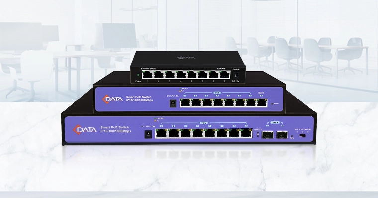
A network switch may be used to aggregate OLT uplinks, support VLAN forwarding, improve access network scalability, and connect multiple access devices to the core network.
The difference is mainly scale:
Deployment Type | OLT Connection Design | Typical Scenario |
Small network | OLT connects to one switch or router | Hotel, apartment, small ISP, campus |
Medium network | Multiple OLTs connect to aggregation switch | Community broadband, enterprise park |
Large carrier network | OLTs connect to redundant aggregation/core systems | ISP, telecom operator, city-level FTTH |
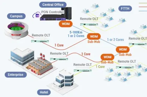
Distributed access network | Outdoor or remote OLTs connect back to aggregation nodes | Rural FTTH, remote communities, outdoor cabinets |
Before connecting an OLT to switches, engineers should confirm technical compatibility and network design details.
Important checks include:
Uplink port speed and optical module type
Switch port capacity
VLAN and QinQ support
LACP or link aggregation support
MTU size
QoS policy compatibility
Multicast and IGMP settings
Management VLAN design
IP addressing and gateway design
Redundancy protocol
Optical module distance and fiber type
Monitoring and alarm integration
The OLT, switch, router, and management platform should be planned as one system. If each device is configured separately without a clear network architecture, the result may be unstable services, difficult troubleshooting, or inefficient bandwidth usage.
An OLT connects to the core network through uplink ports and usually integrates with aggregation switches or routers. On the access side, it communicates with ONUs through PON ports. On the network side, it forwards subscriber traffic to the carrier or enterprise backbone through Ethernet uplinks.
In carrier network architecture, the OLT acts as the first aggregation point for PON users. The switch provides traffic aggregation, VLAN forwarding, redundancy, and connection to the carrier’s core network. Together, the OLT and switch form the bridge between the fiber access network and the core network.
For reliable deployment, network planners should consider uplink capacity, VLAN structure, switch compatibility, redundancy, QoS, multicast, and future bandwidth expansion. A well-designed OLT-to-switch architecture can improve FTTH network stability, scalability, and service quality.
An OLT connects to the core network through uplink ports. These uplink ports usually connect to aggregation switches, Layer 3 switches, routers, BRAS/BNG systems, or metro Ethernet network equipment.
Yes. In many networks, the OLT connects directly to an aggregation switch or Layer 3 switch through GE, 10GE, 25GE, 40GE, or 100GE uplink ports.
An OLT PON port connects downward to ONUs through optical splitters. An uplink port connects upward to switches, routers, or the core network.
VLANs separate users, services, and traffic types. They help operators carry broadband, IPTV, VoIP, enterprise, and management traffic through the same uplink while keeping services logically separated.
Yes. In medium and large networks, multiple OLTs often connect to one or more aggregation switches. This helps centralize traffic forwarding and simplify network expansion.
If the uplink bandwidth is too small, users may experience congestion, slow internet speed, packet loss, or unstable service during peak hours, even if the PON side has enough access capacity.
For carrier, enterprise, campus, and business-critical networks, redundant uplinks are recommended. They can improve service reliability if one uplink port, fiber path, or switch fails.