 Optical Transport Networking Solution
 FTTH Solution
 Home Networking Solution
 POL Solution
 Outdoor OLT Solution
 More
More
 Brand News
 Product News
 Tech Blogs
 CMS
CMS
 Tech Support
 Document Download
 Software Download
 FAQ
FAQ
 Training Center
 About Us
 Careers
 Partners
 Quality Assurance
 Video Center


This website uses cookies to ensure you get the best experience. Some cookies are essential, while others help
us improve your experience by analyzing data or showing personalized content.
For details, please see our
Privacy Policy.

In a PON access network, the OLT is the central device that connects the operator's aggregation network to user-side ONUs or ONTs. However, an OLT is not only a box with fiber ports. It is part of a complete access architecture that includes the core network, aggregation switches, OLT uplinks, PON ports, passive optical splitters, ONUs, service platforms and management systems.
For ISPs, telecom operators, hotels, campuses, smart communities and enterprise fiber projects, understanding OLT architecture and network topology is important before selecting equipment. A clear topology helps planners decide where the OLT should be installed, how many PON ports are needed, how uplinks should be designed, how ONUs are connected and how services should be separated.
This article explains the basic OLT architecture, common OLT network topology models, and key design points for building a stable PON access network.
OLT architecture refers to the way an Optical Line Terminal is structured and connected inside a PON access network. It includes the hardware structure of the OLT, the logical service architecture and the network topology around the OLT.
A typical OLT architecture includes:
Core or aggregation network connection
OLT uplink ports
Switching and control system
PON service ports
Optical distribution network (ODN)
Optical splitters
ONUs or ONTs
Management system
Service platforms for internet, IPTV, VoIP or enterprise access
According to Broadband Forum TR-156, the OLT is the first aggregation point in GPON access scenarios. This description is useful because it shows that the OLT is not only a fiber access device. It is also the point where traffic from multiple ONUs are aggregated before traffic moves toward the upper-layer network.
For example, a C-Data OLT can be deployed as the access aggregation platform in FTTH, FTTB, campus, hotel, rural broadband and ISP networks.
An OLT system usually includes physical hardware, service interfaces, control functions and management functions. The actual structure depends on whether the OLT is a fixed model, mini model, outdoor model or chassis-based platform.
Common OLT system parts include:
Component | Function |
PON ports | Connect to optical splitters and ONUs |
Uplink ports | Connect to aggregation switches, routers or core network |
Control module | Handles system control and service processing |
Switching fabric | Forwards traffic between PON side and uplink side |
Power module | Supplies power to the OLT system |
Fan or thermal system | Maintains operating temperature |
Management interface | Supports web, CLI, EMS, SNMP or remote management |
Service boards | Provide PON or uplink interfaces in modular OLT systems |
A fixed OLT may integrate these functions into one compact device. A chassis OLT may use separate service boards, control boards, power modules and fan modules. In large networks, modular architecture is useful because operators can expand PON capacity or uplink capacity as the subscriber base grows.
In PON network topology, the OLT sits between the aggregation network and the ODN. It connects upward to aggregation switches or routers and downward to ONUs through passive optical splitters.
A basic topology looks like this:
Core network
↓
Aggregation switch / router
↓
OLT
↓
Optical splitter
↓
ONU / ONT
↓
User devices
In this topology, the OLT has two main directions:
Uplink direction: connects the OLT to aggregation switches, routers, BNG, BRAS or the core network.
Downstream direction: connects the OLT to ONUs or ONTs through optical splitters and fiber cables.
A GPON OLT typically manages downstream and upstream traffic between the central office network and many user-side ONUs. According to ITU-T G.984.3, GPON transmission convergence includes upstream time division multiple access and dynamic bandwidth allocation mechanisms, which help the OLT coordinate multiple ONUs sharing the same PON infrastructure.
The most common OLT network topology is a point-to-multipoint PON topology. The OLT connects to an optical splitter, and the splitter distributes signals to multiple ONUs.
A simplified point-to-multipoint topology is:
OLT PON port
↓
1:N optical splitter
↓
Multiple ONUs / ONTs
This topology is different from a traditional Ethernet switch topology. In Ethernet switching, many devices may connect through separate switch ports or cascaded switches. In PON, one OLT PON port can serve many ONUs through passive optical splitters.
The point-to-multipoint structure provides several advantages:
Reduces active equipment in the ODN
Allows one PON port to serve multiple users
Supports centralized management from the OLT side
Reduces on-site power requirements
Supports FTTH, FTTB and FTTx access models
Makes fiber access more scalable in many deployment scenarios
However, the topology must be planned carefully. Split ratio, optical power budget, fiber distance and user bandwidth demand all affect the overall network performance.
OLT, ONU and ODN are the three basic parts of a PON access system.
Element | Full Name | Network Position | Main Function |
OLT | Optical Line Terminal | Central side | Controls PON access and connects to the aggregation network |
ODN | Optical Distribution Network | Between OLT and ONU | Provides passive optical path through fiber and splitters |
ONU / ONT | Optical Network Unit / Terminal | User side | Receives optical signal and provides user interfaces |
The OLT sends downstream data through the ODN. The ONU receives the data and provides services to users through Ethernet, Wi-Fi, POTS, CATV or other interfaces. In the upstream direction, the ONU sends traffic back to the OLT according to the time windows assigned by the OLT.
An ONU should be selected according to the service requirement, such as broadband internet, IPTV, VoIP, Wi-Fi access, CATV or enterprise access.
An OLT connects to the core or aggregation network through uplink ports. These uplink ports may use GE, 10GE, 25GE, 40GE or 100GE interfaces depending on the OLT model and network scale.
A typical upstream topology is:
OLT uplink port
↓
Aggregation switch
↓
Router / BNG / BRAS
↓
Core network / Internet
The aggregation switch collects traffic from one or more OLTs and forwards it toward the aggregation network. In larger carrier networks, multiple OLTs may connect to redundant aggregation switches for higher reliability.
A network switch can be used to aggregate OLT uplinks, separate VLAN traffic and connect the OLT access layer with routers or service platforms.
When designing OLT uplinks, planners should check:
Uplink speed
Number of uplink ports
Optical module type
Aggregation switch capacity
VLAN and QinQ support
LACP or link aggregation support
Redundant uplink design
Peak-hour traffic demand
Future bandwidth growth
If the PON side has many users but the uplink side is too small, the network may experience congestion even if the OLT PON ports are not fully loaded.
Different projects use different OLT topology models. The best model depends on user density, access distance, equipment room availability and maintenance strategy.
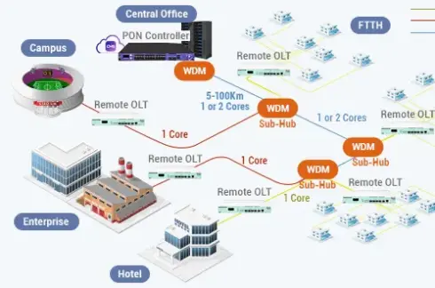
In centralized topology, the OLT is installed in a central office, equipment room or main access node. Fiber is distributed from the central site to multiple users, buildings or communities.
This model is suitable for:
Dense urban FTTH
Residential communities
Campuses
Hotels
Centralized ISP access rooms
Planned building networks
The advantage is easier centralized maintenance. The limitation is that fiber routes may become longer when users are scattered.
In distributed topology, OLTs are placed closer to users, such as in outdoor cabinets, village nodes, buildings or edge access sites.
This model is suitable for:
Rural broadband
Remote communities
Outdoor cabinets
Industrial parks
Smart city access nodes
Scattered user areas
The advantage is shorter access distance and flexible coverage. The challenge is that operators need strong remote management and reliable field deployment.
In some networks, OLTs connect to redundant aggregation switches or dual uplinks. This improves reliability when one fiber path or switch port fails.
This model is suitable for:
Carrier access networks
Enterprise parks
Government networks
Campus backbone
Business-critical broadband access
Redundancy should be planned according to service importance and budget. Not every small project needs complex protection, but carrier and enterprise networks often require it.
OLT architecture must support different services, such as internet access, IPTV, VoIP, public Wi-Fi, surveillance and enterprise private access. These services are usually separated through VLANs, QoS policies and service profiles.
A common service architecture may look like this:
Service | OLT Design Focus |
Internet access | Subscriber VLAN, bandwidth profile, PPPoE or IPoE model |
IPTV | Multicast VLAN, IGMP, QoS and video traffic control |
VoIP | Voice service VLAN, low latency and ONU voice port provisioning |
Surveillance | Stable upstream bandwidth and service isolation |
Enterprise access | Dedicated VLAN, QoS and security policy |
Management | Separate management VLAN for OLT and ONU monitoring |
The OLT forwards service traffic between the ONU and service platforms. It does not usually act as the final internet gateway, IPTV server or voice platform. Instead, it provides the access control and aggregation layer that connects users to those services.
For FTTH networks, the OLT usually connects to many home ONUs through optical splitters and drop fibers. The design focus is user scale, split ratio, bandwidth package and remote ONU management.
For FTTB networks, the OLT connects to building-side ONUs, MDUs or access terminals. The final connection inside the building may use Ethernet or other in-building wiring. The design focus is building-level traffic aggregation, tenant separation and internal wiring quality.
A practical comparison:
Item | FTTH OLT Topology | FTTB OLT Topology |
Fiber endpoint | Home or premises | Building equipment room or floor box |
User-side device | Home ONU / ONT | Building ONU, MDU or access terminal |
Design focus | Many individual subscribers | Building-level aggregation |
Service control | Per-user service profile | Per-building or per-tenant service design |
Best for | Residential broadband | Apartments, hotels, offices, schools |
Both FTTH and FTTB can use the same OLT platform if the PON standard, ONU model, service profile and network topology are planned correctly.
Before designing OLT topology, engineers should evaluate both physical infrastructure and service requirements.
Important checks include:
Number of users
User distribution
FTTH, FTTB or FTTC architecture
PON standard, such as GPON or XGS-PON
PON port count
Split ratio
Fiber distance
Optical power budget
Uplink bandwidth
Aggregation switch capacity
VLAN and service plan
ONU compatibility
Management platform
Redundancy requirement
Indoor or outdoor deployment environment
A good OLT topology should be easy to expand, easy to manage and aligned with real user demand. Overly simple topology may limit future growth. Overly complex topology may increase cost and maintenance difficulty.
OLT architecture is the structural foundation of a PON access network. It includes the OLT hardware, uplink design, PON ports, ODN, ONUs, service profiles and management system. OLT network topology describes how these elements are connected in real deployment.
The most common topology is point-to-multipoint, where one OLT PON port connects to multiple ONUs through optical splitters. The OLT connects upward to aggregation switches and routers, and downward to user-side ONUs. Depending on deployment needs, operators may choose centralized OLT topology, distributed OLT topology or redundant uplink topology.
For ISPs, telecom operators, campuses, hotels and smart communities, a successful OLT architecture should balance access capacity, uplink bandwidth, optical power budget, service separation, ONU compatibility, remote management and future upgrade planning.
OLT architecture refers to the hardware, service and network structure around an Optical Line Terminal. It includes uplink ports, PON ports, control functions, optical distribution network, ONUs and management systems.
OLT network topology describes how the OLT connects to the core network, optical splitters, ONUs and user devices. The most common PON topology is point-to-multipoint.
The OLT is located on the central side of the PON network, usually in a central office, equipment room, access node, cabinet or data room.
The OLT connects to ONUs through PON ports, optical fiber and passive optical splitters. One OLT PON port can serve multiple ONUs depending on split ratio and optical power budget.
The OLT connects to the core or aggregation network through uplink ports. These ports usually connect to aggregation switches, routers, BNG, BRAS or service platforms.
Centralized OLT topology places the OLT in a main equipment room or central office. Distributed OLT topology places OLTs closer to users, such as in cabinets, buildings or remote nodes.
OLT topology planning affects bandwidth, reliability, optical power budget, user expansion, service separation and maintenance efficiency. Poor topology design can cause congestion, optical loss problems or difficult troubleshooting.